
Shelly Pro 1 v.1
Shelly Pro 1 v.1 is a modification of Shelly Pro 1 (SPSW-001XE16EU).
Shelly Pro 1 v.0 is now obsolete and out of sale.
Download Shelly Pro 1 multi-language printed user manual
Differences with Shelly Pro 1 v.0 are marked by the ≠ symbol in the text below.
Main changes
- Power supply: no more 12 VDC option.
- Relay: no more DC switching.
- Connectors: 3-terminal connectors are replaced by 2-terminal ones.
- PCBs: relay 2-layer PCBs are replaced by 4-layer ones for better thermal performance.
- LAN: improved high voltage electrical distances.
- Plastics shell: improved dielectric performance.
Device identification (≠)
- Device name: Shelly Pro 1 v.1
- Device model: SPSW-201XE16EU
- Device SSID: ShellyPro1-XXXXXX
Short description
Shelly Pro 1 is a DIN rail mountable smart switch with potential-free contacts. Enhanced with all the gen2 firmware flexibility and LAN connectivity, it provides professional integrators with many more options for end customer solutions. It can work standalone in a local Wi-Fi network or be operated through cloud home automation services.
Shelly Pro 1 can be accessed, controlled, and monitored remotely from any place where the user has internet connectivity, as long as the device is connected to a Wi-Fi router and the Internet.
It features an embedded Web Interface for monitoring, controlling, and adjusting device settings.
Main applications
- Residential
- MDU (Multi Dwelling Units – apartments, condominiums, hotels, etc.)
- Light commercial (small office buildings, small retail/restaurant/gas station, etc.)
- Government/municipal
- University/college
Integrations
- Alexa
- Samsung SmartThings
Simplified internal schematics (≠)
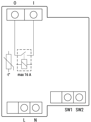
Device electrical interfaces
Inputs
- 2 switch/button inputs on screw terminals: SW1 and SW2
- 2 power supply inputs on screw terminals: 1 N and 1 L
- 1 relay input: I
Outputs
- 1 relay output: O
Ethernet port
- 1 RJ45 connector
⚠ CAUTION! Plug in or unplug the LAN cable only when the device is powered off! The LAN cable connector must not be metallic in parts touched by the user during connection/disconnection.
Add-on interface
- Shelly proprietary serial interface
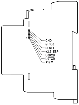
⚠ CAUTION! High voltage on the add-on interface when the device is powered!
Connectivity
- Ethernet
- Wi-Fi
- Bluetooth
Safety features
- Overheating protection
Supported load types
- Resistive (incandescent bulbs, heating devices)
- Capacitive (capacitor banks, electronic equipment, motor start capacitors)
- Inductive with RC Snubber (LED light drivers, transformers, fans, refrigerators, air-conditioners)
User interface
Inputs
- One tactile dome button
- Press and hold 5 sec to reboot
- Press and hold 10 sec to factory reset
Outputs
- LED indication
- Power (red): Red light indicator will be on if power supply is connected.
- Wi-Fi (varies):
- Blue: AP mode
- Red: STA mode and not connected to Wi-Fi network
- Yellow: STA mode, connected to Wi-Fi, but not to Shelly Cloud (or Cloud disabled)
- Green: STA mode, connected to Wi-Fi and Shelly Cloud
- Flashing Red/Blue: OTA update in progress
- LAN (green): Green light indicator will be on if LAN is connected.
- Out (red): Red light indicator will be on if the Output relay is closed.
Specifications (≠)
| Type | Value |
|---|---|
| Physical | |
| Size (HxWxD) | 94 × 19 × 69 ±0.5 mm / 3.70 × 0.75 × 2.71 ±0.02 in |
| Weight | 63 g / 2.22 oz |
| Mounting | DIN rail |
| Screw terminals max torque | 0.4 Nm / 3.54 lbin |
| Conductor cross section | 0.5 to 2.5 mm² / 20 to 14 AWG (green connector) 0.5 to 1.5 mm² / 20 to 16 AWG (blue connectors) |
| Conductor stripped length | 6 to 7 mm / 0.24 to 0.28 in (green connector) 5 to 6 mm / 0.20 to 0.24 in (blue connectors) |
| Shell material | Plastic |
| Color | Blue |
| Environmental | |
| Ambient temperature | -20 °C to 40 °C / -5 °F to 105 °F |
| Humidity | 30 % to 70 % RH |
| Max. altitude | 2000 m / 6562 ft |
| Electrical | |
| Power supply voltage AC | 110 - 240 V |
| Power supply voltage DC | N/A |
| Power consumption | < 3 W |
| Neutral not needed | No |
| Output circuits ratings | |
| Max switching voltage AC | 240 V |
| Max switching voltage DC | N/A |
| Max switching current AC | 16 A |
| Max switching current DC | N/A |
| Sensors, meters | |
| Internal-temperature sensor | Yes |
| Radio | |
| RF band | 2400 - 2495 MHz |
| Max. RF power | <20 dBm |
| Wi-Fi protocol | 802.11 b/g/n |
| Wi-Fi range | Up to 30 m / 100 ft indoors and 50 m / 160 ft outdoors (Depends on local conditions) |
| Bluetooth Protocol | 4.2 |
| Bluetooth range | Up to 10 m / 33 ft indoors and 30 m / 100 ft outdoors (Depends on local conditions) |
| MCU | |
| CPU | ESP32-D0WDQ6 |
| Flash | 8 MB |
| Firmware capabilities | |
| Schedules | 20 |
| Webhooks (URL actions) | 20 with 5 URLs per hook |
| Scripting | Yes |
| MQTT | Yes |
| CoAP | No |
Basic wiring diagram (≠)
| Resistive load | Inductive load and RC snubber |
|---|---|
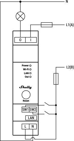 | 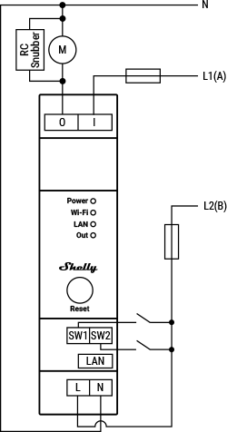 |
Legend
| Terminals | Description | Wires | Description |
|---|---|---|---|
| I | Load circuit input terminal | L1(A) | Load circuit live (110–240 V) wire |
| O | Load circuit output terminal | L2(B) | Device power supply live (110–240 V) wire |
| SW1, SW2 | Switch/button input terminals | N | Neutral wire |
| L | Live (110–240 V) terminal | ||
| N | Neutral terminal | ||
| LAN | Local Area Network RJ45 connector |
Shelly Smart Control
Shelly Web user interface
Troubleshooting
...
Web Interface guide
Read the Shelly Pro 1 web interface guide
Components and APIs
Printed user guide
- Shelly Pro 1 multilingual printed user and safety guide
- Ръководство за употреба и безопасност (Bulgarian)
Compliance
- Shelly Pro 1 multilingual EU declaration of conformity (2025-07-22)
- Shelly Pro 1 UK PSTI ACT Statement of compliance
- Shelly PRO 1 & PRO 2 AU NZ Certificate for Suitability